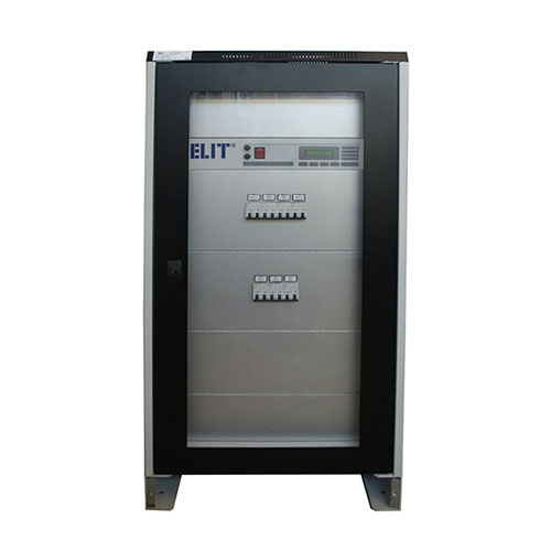
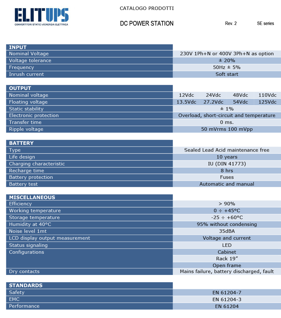
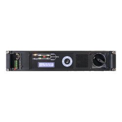
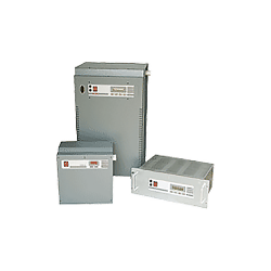
The DC power station SE series are the result of a long experience in the field of UPS as well as in this specific. The DC Power Station SE series is an electronic device that transforms the AC power into direct current with a sinusoidal wave at 12Vdc, 24Vdc, 48Vdc and 110Vdc. Typical applications are telephone systems, auxiliary cabin power supply, substations, LV / MV switchboards and emergency lighting. The DC power station ensures continuity of power even in the event of a power failure, thanks to the batteries connected to the station. The switching operation with input PFC minimizes the distortion of the current absorbed by the mains and allows to obtain high efficiency, therefore low dissipation and energy saving. The products fully meet the requirements of the CEI 103-1 / 11 standards for telephone systems too.
Description
The SE dc power station series has been designed to supply direct current loads “without interruption” (no transfer time) either in the presence or in the absence of the electrical mains. In the presence of main, the dc power station converts the input voltage to DC voltage and provides galvanic isolation between input and output. The use of a microprocessor allows the control of the output voltage, of the current absorbed by the load, of the batteries, and the disconnection of the same in case of excessive discharge.
The microprocessor, with which the dc power station is equipped, with the support of analog and digital sensors, controls all the electrical parameters such as voltages, currents that will be displayed on the synoptic panel. When the microprocessor detects an anomaly, it displays it on the display, stores it in the power history, and activates the corresponding alarm relay.
All of these system parameters and the associated alarm messages can be transmitted either through a dry contact interface or via an accessory SNMP card.
- Input voltage: 230V single-phase, 50Hz (400V 3Ph+ N on request).
- Electronic stabilization, output voltage and frequency independent by the input.
- Continuous operation.
- Transfer time zero in mains failure situation.
- Isolation transformer.
- Switching technology.
- LCD display for output measurements.
- Insulation controller as option.
- Automatic and manual battery test.
- Operation in parallel with other units.
- Available in cabinet or rack configuration.
- Back up time or higher powers on request.
- Dry contacts for remote alarms.
- Optional SNMP interface.

The SE dc power station has provided with the following operating and alarm signals:
- Mains presence.
- Battery in discharge.
- System Failure.
- Battery control button.
- Voltage / current button.
- Battery Exclusion buttons.
- Power switch.
- Ethernet connector for LAN interface if required.
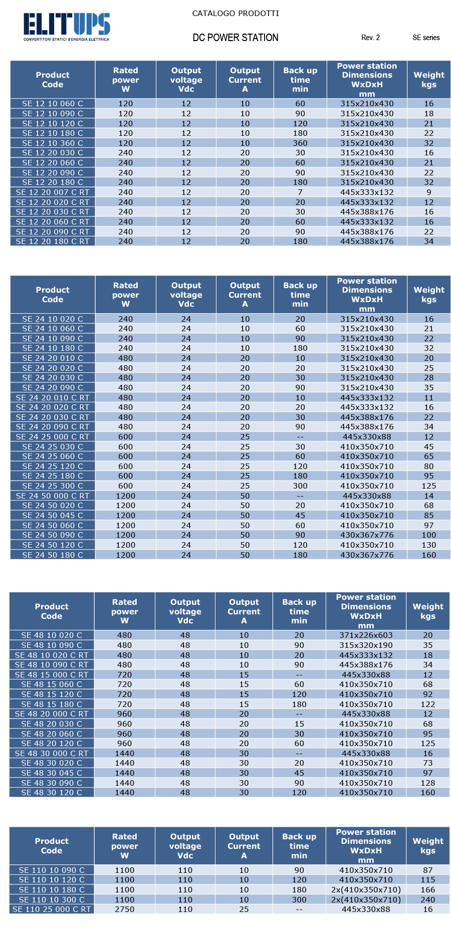
The SE dc power stations are available with the following output voltages:
SE 12Vdc: powers available from 5A to 40A
SE 24Vdc: powers available from 5A to 600A
SE 48Vdc: powers available from 5A to 600A
SE 110Vdc: powers available from 5A to 200A
SE 220Vdc: powers available from 5A to 200A
Back up time: from 10 minutes to 4 hours.
All devices are equipped with VRLA batteries, 10 years lifetime design.
By using the assemblies used in standard equipment, and therefore with proven functionality, custom realization are available.
The SE dc power station is provided with the following communication ports:
Dry contact interface
To remote alarms as mains, low battery and general alarm.
SNMP
Interface for the optional LAN network connection, which controls all the operating parameters and manages the tele-diagnosis service. The Lan network uses the TCP / IP protocol to control the power station using the Ethernet network from either a local or WAN network. The system may also manages a gateway (router) to be able to access remotely via the Internet. Access to the network is done by using a browser or other programs such as Telnet and typing the IP address set or in the local Windows environment the default NETBIOS name of the machine.
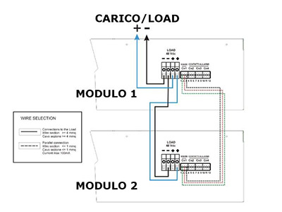
The SE dc power station may be paralleled for power capacity or for redundancy up to 8 units to increase the power capacity or configuring a parallel redundant power station system. The standard version is not provided with this feature which is optional and field upgradable.

The input and output terminal board is located on the back of the device.
On the back panel there are:
- Load output connector: no.2 negative terminals + no.2 positive terminals in parallel.
- Internal battery protection fuses and load.
- CN1 green terminal for parallel connection with other devices.
- Green terminals from CN2 to CN4 for remote alarm signaling.
- Mains input protection fuses.
- 230Vac input socket.


